

 Listen Now
  Add to Playlist

By Jeff Wright — Vice President of Technical Services
Ted Moores and his company, Bear Mountain Boats, build wood epoxy strip plank canoes, manufacture kits, and publish books on building strip plank canoes and kayaks. This method of construction provides a very light yet stiff structure and also enables the hull shape to have compound curves. Moores has 30 years of experience and his designs have logged many safe miles. He understands the forces boats are subjected to when paddled on the water and during transportation.
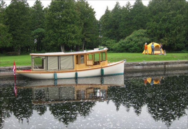
Photo above: The Bear Mountain 30 Hybrid Electric Launch was launched in June. The launch is a beautiful and efficient way to cruise the lakes and waterways around Peterborough, Ontario, home to Bear Mountain Boats. To see a video of the boat and detailed construction photos, visit www.bearmountainboats.com.
Bear Mountain Boats expanded into a new area when they started construction of a 30′ launch. This boat would be powered by a 5 kw motor and would achieve speeds of 6 knots. Moores knew that the displacement and speed of this boat meant the potential impact loads from accidental beaching and flotsam would be much more severe than with his lightweight canoes. Instead of just overbuilding the boat, Ted used composite materials to optimize its strength with only a minimal increase in weight.
The Test
Since Ted Moores has been a long-time WEST SYSTEM® Epoxy customer, he was well aware of our material testing capability. When he contacted us he had already decided on the wood species, White Cedar, and thickness, ¾”, but had not determined the amount and orientation of the fiberglass sheathing. He knew that the amount of fiberglass would play a significant role in the boat’s impact performance. We suggested using our Hydromat Test in combination with an impact test to evaluate the effect of damage on a variety of laminate combinations.

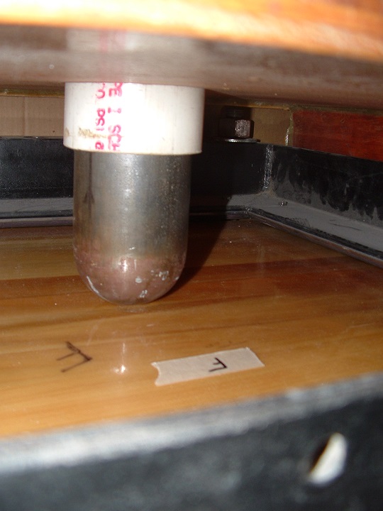
The stiffness of the panels would first be measured in accordance with ASTM D-6416. The panels were then damaged using our impact test fixture (Figure 1a) which applies the same impact force to a secured panel by dropping a blunt-nosed weight (Figure 1b) from a fixed distance. After the panels were all struck (and damaged) by the same force, the stiffness would be measured again using the Hydromat to evaluate the effect of the damage.
The Results
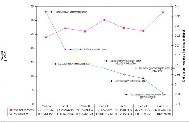
At first glance, the results seem to indicate that more layers of fiberglass help retain stiffness after an impact, but when fiber orientation is considered, the impact performance can be improved without increasing weight. In Figure 2, the increase in deflection when compared to weight is generally lower when the sheathing consists of 45° oriented fibers. Even though the panels are in the shape of a square, the fiber orientation had a significant effect due to the grain direction of the wood strips.
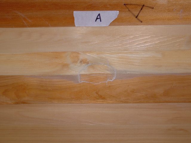
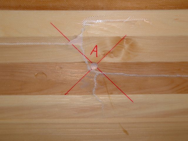
The pictures of Panel A, one layer of 6oz fiberglass cloth oriented at 90° on each side, show a very small area of damage on the impact side (Figure 3A) but the reverse side (Figure 3B above) has a large laminate failure. Much of the laminate failure occurred in the fibers oriented across the wood grain, indicating that additional cross-grain strength would be beneficial.
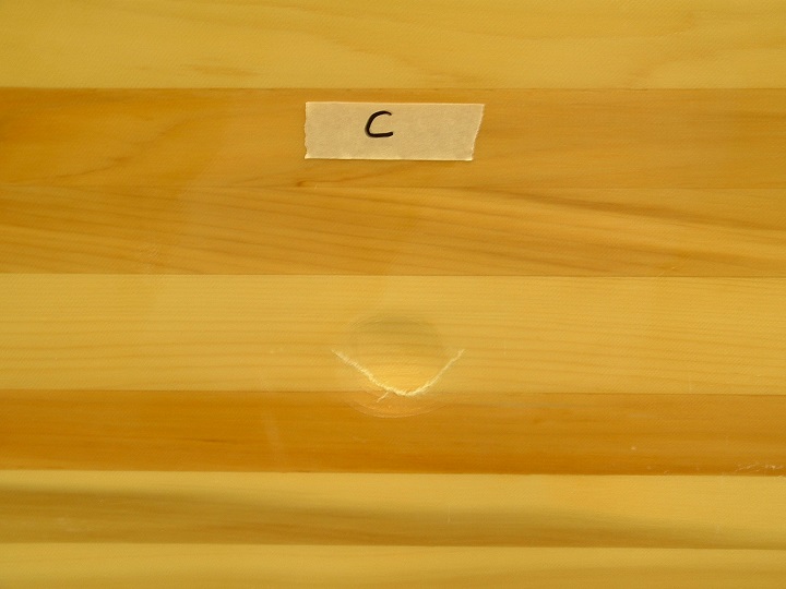
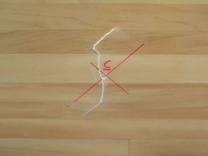
Panel C (Figure 4A, impact side, and 4B, reverse side, above), which had an additional layer of 6oz cloth on each side oriented 45° to the wood grain, retained significantly more stiffness than Panel A. The other panels with fiberglass oriented at 45° to the wood grain also retained more stiffness than panels with the same amount of fabric oriented at 90° to the wood grain.
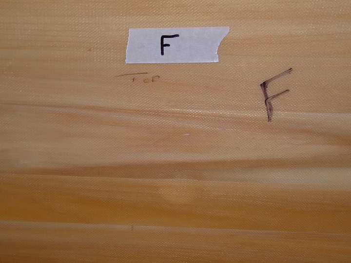
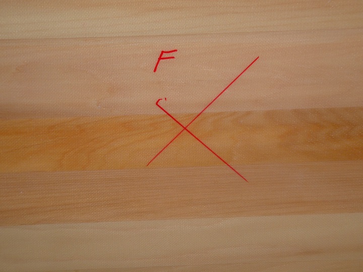
The combination with the best balance between weight and damage resistance appears to be Panel F (Figure 5a, impact side and 5B, reverse side, above). It had almost the damage tolerance of Panel G, which did not lose any stiffness from the impact, but Panel F weighs much less.
It is interesting to note the amount of damage that occurred on the side opposite from the impact. If this had been an impact on an actual hull, the visible damage on the outside surface would be very misleading. As we have suggested for both wood strip construction and balsa and foam-cored composites, be sure to thoroughly investigate for damage. A small divot on the outside could indicate significant damage on the opposite side. Looking at Panel A in Figure 3A, the impact certainly does not indicate the amount of damage on the opposite side that resulted in a 37% increase in deflection (Figure 3B).
Conclusion
This series of panels was ideal for testing for damage tolerance. All panels had the same wood strips, and the same type of fiberglass fabric, and all were laminated in the same shop. The variables were the number of layers and fiber orientation. Thanks to Ted’s excellent craftsmanship and a well-designed test, we were able to offer Bear Mountain Boat’s data that was helpful during the construction of this boat. Hopefully, other WEST SYSTEM users will also take advantage of this information.